What is the difference between a membrane element and a shell element?
What Is the Difference Between a Membrane Element and a Shell Element?
Two commonly used elements in structural analysis are membrane elements and shell elements. While both are crucial elements in finite element analysis (FEA), they serve specific purposes and display distinct behaviors under different loading conditions.
A membrane element and a shell element are both types of finite elements used in structural analysis and engineering simulations, but they serve different purposes and are utilized in different types of analyses. Here is a brief overview of each:
Membrane Element:
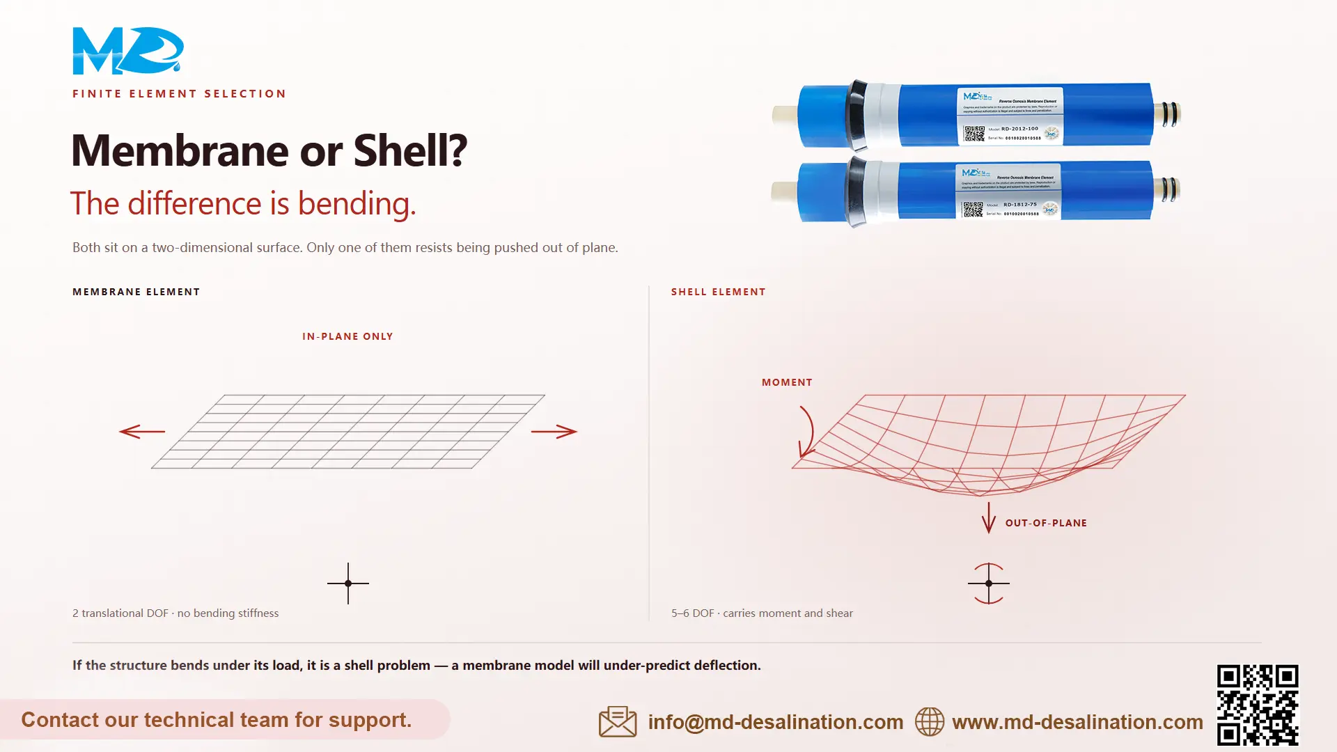
· Membrane elements are used to model thin structures subjected primarily to in-plane loads, such as tension, compression, or shear, with negligible bending.
· They are commonly used to analyze and design structures like membranes, thin shells, and flat plates, where bending stiffness is negligible compared to in-plane stiffness.
· Membrane elements typically have no bending resistance and are characterized by their in-plane properties, such as stiffness and material properties.
· They are represented by two-dimensional elements with only translational degrees of freedom (i.e., displacements in the x and y directions).
Shell Element:
· Shell elements are used to model thin or curved structures that are subjected to both in-plane and out-of-plane loads, including bending moments, shear forces, and membrane forces.
· They are appropriate for analyzing structures like shells, curved panels, and other thin-walled components where both bending and membrane effects are significant.
· Shell elements have bending resistance and can accurately capture the behavior of thin structures experiencing bending, membrane, and shear deformations.
· They are represented by three-dimensional elements with translational and rotational degrees of freedom (i.e., displacements and rotations in all three directions).
In summary, the primary difference between a membrane element and a shell element lies in their intended use and the types of structural behavior they are designed to capture. Membrane elements are ideal for modeling thin structures subjected primarily to in-plane loads, while shell elements are more versatile and can accurately represent the behavior of thin or curved structures experiencing both in-plane and out-of-plane loads, including bending.
Introduction to Finite Element Analysis (FEA)
Before delving into the disparities between membrane and shell elements, it is essential to grasp the concept of finite element analysis itself. FEA is a numerical method used to simulate the behavior of structures and systems under different conditions. It divides complex structures into smaller, simpler elements to facilitate analysis, making it a powerful tool for engineers in various fields.
Understanding Membrane Elements
Membrane elements are primarily utilized to model thin structures subjected to in-plane loads. These elements are ideal for analyzing structures like membranes, thin plates, and shells, where stresses primarily act within the plane of the element. In essence, membrane elements simulate behavior similar to that of a stretched fabric, where loads are distributed uniformly across the surface.
Key Characteristics of Membrane Elements
One of the defining characteristics of membrane elements is their ability to carry in-plane loads while neglecting bending effects. This simplifies analysis for structures where bending is negligible compared to in-plane loads, such as tensioned fabric roofs or thin membranes. Membrane elements are often represented by a network of interconnected nodes, allowing engineers to accurately model complex geometries.
Applications of Membrane Elements
Membrane elements find extensive applications in various industries, including architecture, aerospace, and civil engineering. For instance, they are commonly used in the design and analysis of inflatable structures, tensioned fabric roofs, and lightweight architectural membranes. Their ability to accurately predict the behavior of such structures under different loading conditions makes them indispensable in the field of structural engineering.
Understanding Shell Elements
While membrane elements focus on in-plane behavior, shell elements encompass both in-plane and out-of-plane deformations, making them suitable for analyzing thin-walled structures subjected to complex loading conditions. Unlike membrane elements, shell elements consider the bending stiffness of the structure, providing a more comprehensive representation of its behavior.
Key Characteristics of Shell Elements
Shell elements exhibit both membrane and bending behavior, making them versatile for analyzing a wide range of structures, including shells, curved panels, and pressure vessels. These elements capture the complex interactions between in-plane and out-of-plane loads, allowing engineers to accurately predict stress distribution and deformation patterns.
Applications of Shell Elements
Shell elements are extensively used in industries where thin-walled structures are prevalent, such as automotive, aerospace, and shipbuilding. Engineers rely on shell element analysis to optimize the design of elements like aircraft fuselages, automotive body panels, and ship hulls. By considering both membrane and bending effects, shell elements provide valuable insights into the structural integrity and performance of such elements.
Differences Between Membrane and Shell Elements
While both membrane and shell elements are used to analyze thin structures, they differ in their approach and scope of analysis. Membrane elements focus solely on in-plane behavior, neglecting bending effects, whereas shell elements consider both in-plane and out-of-plane deformations. This fundamental difference dictates their respective applications and suitability for different types of structures.
Choosing Between Membrane and Shell Elements
The choice between membrane and shell elements depends on various factors, including the geometry of the structure, loading conditions, and the level of accuracy required in the analysis. For structures dominated by in-plane loads with minimal bending, membrane elements offer a more efficient and accurate solution. On the other hand, for complex structures subjected to combined in-plane and out-of-plane loads, shell elements provide a more comprehensive analysis.
Choosing between membrane and shell elements depends on the specific structural characteristics and loading conditions of the system being analyzed:
· Geometry and Thickness: If the structure is thin and flat, with minimal bending or out-of-plane deformation, membrane elements may be more appropriate. If the structure has curvature or varying thickness, and bending or out-of-plane deformation is significant, shell elements may be more suitable.
· Loading Conditions: If the primary loads are in-plane forces such as tension, compression, or shear, membrane elements may suffice. If the structure is subjected to bending moments, shear forces, and membrane forces simultaneously, shell elements may be necessary to capture the combined effects accurately.
· Accuracy Requirements: Membrane elements provide simplified models suitable for linear elastic analysis of thin structures with minimal bending effects. Shell elements offer higher accuracy and can capture both bending and membrane effects, making them more suitable for nonlinear analyses.
· Computational Efficiency: Membrane elements are computationally efficient and require fewer degrees of freedom compared to shell elements, making them suitable for large-scale analyses. Shell elements are more computationally demanding but offer higher accuracy for modeling thin-walled structures with bending effects.
· Software Capabilities: Check the capabilities of the FEA software being used. Ensure that the software supports both membrane and shell elements and provides accurate results for the intended analysis.
In summary, the choice between membrane and shell elements depends on factors such as geometry, thickness, loading conditions, accuracy requirements, computational efficiency, and software capabilities. It is essential to carefully assess these factors and select the element type that best matches the characteristics of the structure and the objectives of the analysis.
Conclusion
In conclusion, membrane and shell elements are integral components of finite element analysis, each serving a unique purpose in simulating the behavior of thin structures. While membrane elements focus on in-plane behavior and neglect bending effects, shell elements consider both in-plane and out-of-plane deformations, offering a more comprehensive analysis. Understanding the differences between these elements is essential for engineers to make informed decisions in structural analysis and design.
Need professional advice on membrane technology and engineering solutions?
At Xi'an Membrane Desalination International Co., Ltd., we combine advanced membrane manufacturing with rigorous engineering standards. Whether you are selecting the right membrane element for your project or require custom OEM solutions, our technical team is here to support you. Contact us at info@md-desalination.com for expert guidance and product inquiries.
References
1. COMSOL. "Finite Element Analysis." https://www.comsol.com/finite-element-method
2. STRUCTURE Magazine. "Membrane Structures." https://www.structuremag.org/?p=13677
3. ScienceDirect. "Shell Structures." https://www.sciencedirect.com/science/article/pii/B9780750647931500153